CNC Router: Difference between revisions
NitramLegov (talk | contribs) m Location |
outsourced machine specifics to "WorkBee" and "Kress CNC", which will also be defined as CNC Mill from now on (see #267) |
||
| Line 2: | Line 2: | ||
A CNC router is a computerized [[woodworking]] machine - basically a [[router]] mounted on a positioning system. While it may also be able to handle other materials than wood depending on the [[bits]] you use, a proper [[CNC Mill|CNC mill]] is more precise for machining parts out of metals and other non-wood materials. | A CNC router is a computerized [[woodworking]] machine - basically a [[router]] mounted on a positioning system. While it may also be able to handle other materials than wood depending on the [[bits]] you use, a proper [[CNC Mill|CNC mill]] is more precise for machining parts out of metals and other non-wood materials. | ||
To use this machine, you need to familiarize yourself with at least two pieces of software: | To use this type of machine, you need to familiarize yourself with at least two pieces of software: | ||
* a [[CAD]]/[[CAM]] program (e.g. [[Fusion 360]]) | * a [[CAD]]/[[CAM]] program (e.g. [[Fusion 360]]) | ||
** may also be two different programs, one for CAD and one for CAM | ** may also be two different programs, one for CAD and one for CAM | ||
| Line 12: | Line 12: | ||
You can [https://www.opendesk.cc/ make furniture] or even [https://wikihouse.cc/ build a house]. For more ideas, check out the [[CNC Milling Ideas]]. | You can [https://www.opendesk.cc/ make furniture] or even [https://wikihouse.cc/ build a house]. For more ideas, check out the [[CNC Milling Ideas]]. | ||
{{MachineInclusion}} | |||
{{ | |||
}} | |||
==Tips & Tricks == | ==Tips & Tricks == | ||
Revision as of 12:54, 6 September 2022

A CNC router is a computerized woodworking machine - basically a router mounted on a positioning system. While it may also be able to handle other materials than wood depending on the bits you use, a proper CNC mill is more precise for machining parts out of metals and other non-wood materials.
To use this type of machine, you need to familiarize yourself with at least two pieces of software:
- a CAD/CAM program (e.g. Fusion 360)
- may also be two different programs, one for CAD and one for CAM
- a G-Code sender
There is also an interesting new approach of handheld CNC routing coming out which may remove the size constraints that come with any fixed-frame machine.
Uses
You can make furniture or even build a house. For more ideas, check out the CNC Milling Ideas.
WorkBee
| MachineInfoBox Ooznest WorkBee CNC | |
|---|---|

| |
| Synonyms: | DE: CNC-Fräse, CNC-Plattenfräse, Portalfräsmaschine |
| Type: | CNC Router |
| Material: | wood |
| Used with: | 6 mm, 8 mm, 1/4" or 1/8" end mills; some kinds of router bits |
| Location: | CNC Area |
| Access Requirements: | CNC Router Introduction |
| Status: | Working |
| Software: | Fusion360 or other CAM Software |
| Firmware: | RepRapFirmware |
| Manual: | product page, click "documentation" tab |
| Tutors: | NitramLegov Pakue Johannes Luzian Leo Maker-Joe |
| Similar (More or Less): | router, CNC mill |
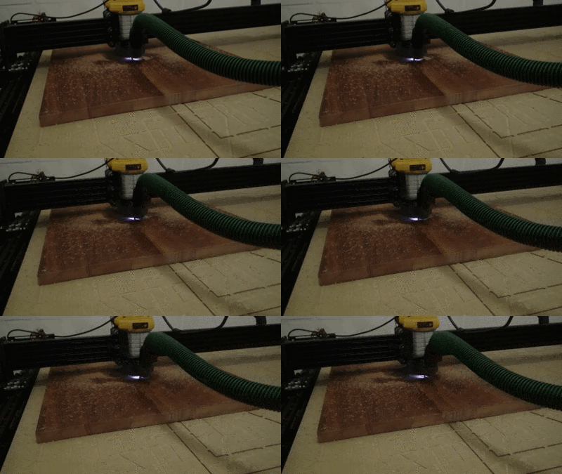
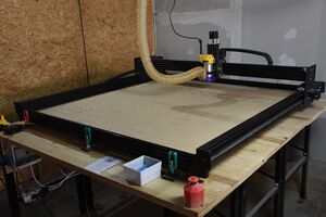
We have a 1500mm x 1500mm version of the WorkBee CNC router, which is based on the Openbuilds OX. It can currently cut sheet material of up to 50 mm thickness on a work area of approximately 1280 × 1200 mm. The surfaced (plangefräste) spoilboard area is 1260 × 1160 (x × y) mm. If you have a rather large piece first test if the raw material is positioned where the router can reach all ends. Your material fitting on the spoilboard is not necessarily a good indicator. The router might stop after 90% of the job and it will be hard/impossible to fix this afterwards. Have the router well above the board and run a gcode file which goes to the farest points, this way you see if it can be reached without ruining your raw material. (It basically routes in mid-air).
Its electronics have been swapped out to run RepRapFirmware and it can now be controlled via a on-machine touch interface or through any local device using its web interface, no extra software or "G-Code sender" needed! :)
Our plans for further improving it up can be found in our "WorkBee CNC" github project - maybe you would like to help.
Issues with complex paths/arc moves
As of now, users are reporting some problems when using the machine to mill complex geometries.
This does not seem to affect milling geometries with straight edges or circles/semicircles. Only Arcs/Splines.
This issue is yet to be fully investigated, the following are an best guess at what is wrong. Further investigation, documentation and fixes are very welcome.
As the Machine was originally shipped with a Mainboard running GRBL, the post-processor for Fusion 360 generates G-Code for GRBL. As we are running a RepRapFirmware board, it doesn't interpret this G-Code the same way which results in jittery movement.
To replicate, create and run a program that involves straight or circular cuts. You should have no problems.
Then, create one involving Arc moves (such as cursive text, spline contours, or similar). The machine reportedly now "jitters" and moves weirdly, resulting in worse quality cuts.
This would probably be fixed by searching for/writing a RepRapFirmware post processor for Fusion 360.
Using the WorkBee CNC
We have various wiki pages documenting how to use the WorkBee CNC. Take a look:
WorkBee Schnittdaten und Fräser Information on cutting parameters and endmill selection (in German)
WorkBee Machine Operation for general machine operation (on/off, starting jobs, jogging, etc)
FreeCAD for setting up FreeCAD and generate a suitable gcode file
Autodesk Fusion 2D Contour Machining for setting up Fusion360 and CAM operations (Creating G-Code for the Machine)
WorkBee organization for keeping things tidy
Workflow
This is just an overview and does NOT replace the personal introduction!
- create the tool paths in a suitable CAM software (e.g. Fusion 360)
- secure your workpiece on the machine's bed
- insert the appropriate collet & bit as defined in your tool paths
- home the machine, jog to your workpiece origin and zero your work coordinates
- Upload your generated G-Code http://10.2.0.3/
- put on personal protection
- Run your Program
- Once the Machine has homed, turn on the spindle & vac on the control panel (only works after homing)
- Be ready to hit the Emergency Stop in case SHTF. Your Program is running!
Router
The router mounted to it is a Dewalt D26200 (GB; known outside Europe as DWP611). You need to consider the sizes of its collets (Spannzangen) when buying your router bits.
- no-load speed: 16000 - 27000 rpm
- max cutter diameter: 30 mm
- available collet diameters:
- 8 mm
- 6 mm
- 1/4 inch (6.35 mm)
- 1/8 inch (3.175 mm)
The collets of the DW613, DW620 and DW621 also fit the router and are easier to get in Germany than the original ones.
RPM Chart
| Dial Setting | Approx. RPM |
|---|---|
| 1 | 16000 |
| 2 | 18200 |
| 3 | 20400 |
| 4 | 22600 |
| 5 | 24800 |
| 6 | 27000 |
Spoilboard
Ooznest recommends a 6mm spoiler board, our first one is 20mm thick. It is mounted to the frame using 4 drop-in T-slot nuts. Cutting into the boards will make it uneven, from time to time it is neccessary to surface the spoiler board again.
The total size of the spoilboard is currently 1445 × 1370 mm.
When there is time, we would like to drill workholding holes into the spoilboard.
Electrics
The Machine received a full electrical overhaul in the first half of 2024, here are its current electrical specifications:
- Duet 3 6HC+ Mainboard running RepRapFirmware
- Web- and touch interface
- MT-2303HS280AW 2.8A NEMA23 Stepper Motors
- Dewalt D26200 Router
Dust Extraction
The Workbee Vacuum automatically turns on with the spindle. We have added a cyclone dust separator before the shop vac so the bulk of the chips should be collected in an easily emptied box rather than the shop vac's bag.
The part that attaches the dust extraction hose to the router is called a "dust shoe". We are currently using this one designed by Patrick. The next version should ideally fit the dust extraction hose without an adapter and include a kind of transparent, flexible "skirt" to optimize the airflow.
Other interesting designs:
Change Log
Please note down all changes you did on the Workbee in case issues are being found it might be easier. Have the newest entry on the top.
| Date | Changed By | Comment | |
|---|---|---|---|
| 9.7.25 | Jochen | Spoilboard leveled, deepend by about 2mm. Previous leveling was not done to the max dimensions, stayed inside the old dimensions. In the future might be good to do the leveling across the complete area. | |
| 9.7.25 | Jochen | config.g file change for step size, since x-direction was about 1.1% off. Old entry: M92 X3.361 Y3.331 Z400 New entry: M92 X3.324 Y3.331 Z400 | |
| 4.6.25 | Jochen | Electric crimps of duet board were faulty, newly crimped. |
OpenBuilds BlackBox CNC
| MachineInfoBox OpenBuilds BlackBox CNC | |
|---|---|

| |
| Synonyms: | DE: CNC-Fräse, CNC-Plattenfräse, Portalfräsmaschine |
| Type: | CNC Router |
| Material: | wood |
| Used with: | 3mm, 6mm, 8mm end mills; some kinds of router bits |
| Location: | CNC Area |
| Access Requirements: | CNC Router Introduction |
| Status: | In Commissioning |
| Firmware: | grbl |
| Manual: | router, BlackBox-4x |
| Tutors: | NitramLegov Pakue Johannes Luzian Leo Maker-Joe |
| Similar (More or Less): | router, CNC mill |
This self-built CNC router arrived at the Space in early 2025 and waits for your help to shine ;-)
This tool is not ready for use yet since not all commissioning steps have been completed. The process is also tracked on GitHub. Feel free to contribute to making it usable, any help is very welcome!
| Task | comment | Status |
|---|---|---|
| Name the tool: | named after its controller | pending |
| Take a picture | - | done |
| Find the manual as PDF | BlackBox_CNC_router_mill.png | pending |
| Documentation | this page, status: in commissioning | pending |
| Print QR-Code | use the MachineQR Factory | pending |
| Introduction | - | pending |
| Security Check | to be done or witnessed by a manager | pending |
| Test | to be done or witnessed by a manager | pending |
| tool's name, owner and approx. value | provide to Johannes for inventorization | pending |
| Last step: make it available | physically and in the wiki - then delete this template | pending |
Using the BlackBox CNC
We have various wiki pages documenting how to use the WorkBee CNC. Maybe some of these can be adapted to include info on the BlackBox? Let's only create extra pages where really necessary:
- WorkBee Machine Operation for general machine operation (on/off, starting jobs, jogging, etc)
- WorkBee organization for keeping things tidy
- Autodesk Fusion 2D Contour Machining for CAM (Creating G-Code for the Machine)
Workflow
just copied from WorkBee so far --------
This is just an overview and does NOT replace the personal introduction!
- create the tool paths in a suitable CAM software (e.g. Fusion 360)
- secure your workpiece on the machine's bed
- insert the appropriate collet & bit as defined in your tool paths
- home the machine, jog to your workpiece origin and zero your work coordinates
- Upload your generated G-Code
- put on personal protection
- Run your Program
- Once the Machine has homed, turn on the spindle & vac on the control panel (only works after homing)
- Be ready to hit the Emergency Stop in case SHTF. Your Program is running!
Router
The router mounted to it is a Mafell FM800 [1]. You need to consider the sizes of its collets (Spannzangen) when buying your router bits.
- no-load speed: 7000 - 25000 rpm
- max cutter diameter: 36 mm
- available collet diameters:
- 8 mm
- 6 mm
- 3 mm
RPM Chart
The RPM value is set on the router via a dial, settings in the g-code are not obeyed. You can change the router RPM value during operation if needed.
| Dial Setting | Approx. RPM |
|---|---|
| 1 | 7000 |
| 2 | 10600 |
| 3 | 14200 |
| 4 | 17800 |
| 5 | 21400 |
| 6 | 25000 |
Spoilboard
workholding options, replacement? -----
Dust Extraction
--- ??? ----
EleksMill
| MachineInfoBox EleksMill | |
|---|---|

| |
| Synonyms: | DE: CNC-Fräse |
| Type: | CNC Router |
| Material: | just foam for now |
| Used with: | 1/8" endmills |
| Location: | 3D Printing Area |
| Access Requirements: | CNC Router Introduction |
| Status: | Working |
| Software: | CAD/CAM software (e.g. Fusion 360); G-code sender |
| Tutors: | NitramLegov Pakue Johannes Luzian Leo Maker-Joe |
| Similar (More or Less): | CNC router |
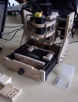
Mitja brought his "EleksMill" CNC router into our Space - it's small, but great for learning the basics of CNC Routing/routing as it shares the same workflow as the large WorkBee.

Important Facts
- 130 × 90 × 40 mm working range (less Z freedom depending on the length of your endmill!)
- there are no endstops
- manually home the mill before a job
- you should use the (X/Y center, Z surface) as your origin
- make sure the size of your part does not exceed the working range!
- motor speed: ???
- compatible shaft diameter: 1/8" (3.175 mm)
- controlled like the CNC router (Fusion 360 or similar CAD/CAM software; G-code sender)
- connection via USB - bring your own laptop!
Workholding
The mill has a 150 × 98 mm bed containing of 4 T-slots. clamping claws or similar workholders can be attached to it using M5 screws.
The current solution is not ideal, but many the workholding options for our larger CNC router should also be suitable if scaled down.
TO DO
- figure out motor speed to calculate proper feedrates
- what else?
Past Issues
- screws/nuts used to come loose due to vibrations
- fixed with loctite or counternuts (where possible)
- Z axis used to be too hard to turn => mill drifted deeper and deeper into the workpiece as upwards movements failed but downward movements were still possible
- was caused by a faulty spring
Tips & Tricks
- to avoid tear-out at the edge of a sensitive workpiece, it may be worthwhile to surround it with some sacrificial material (like MDF) before routing [2]
Materials
(For more details, see "Milling Experiences")
CNC routing is most appropriate for non-metal panels/boards. The exact material might dictate your choice of endmill or router bit!
Cutting certain metals, e.g. millable aluminum, may still be possible with a lot of extra work, but a rigid and liquid-cooled CNC mill would be the proper way to go.
Carbon Fiber
Carbon fiber (CF) dust can be harmful if handled improperly. If you intent to route CF parts on the CNC (like plates for quardrocopter parts) please follow the workflow below:
- Route carbon fiber only in a submerge water path e.g. in a large enough tray (keep enough towels near in case of an 'accident')
- Afterwards filter the water through a coffee filter or similar
- Don't vacuum the dust - instead, wipe it away with a moist towel or use some tape to pick it up
- Only wet sanding
- Keep the parts that came into contact with the carbon fiber dust in a sealed plastic bag until they are discarded
- Discard the remains at a local special waste disposal and don't put them in the garbage!
Helpful Links
- video tutorials:
- Ooznest YouTube channel (pretty new, but specific to our "WorkBee" setup)
- Fusion 360 CAM Tutorial for Beginners by Evan & Katelyn (insert our preferred G-code sender where they use Easel)
- other spaces with (somewhat) similar machines and good approaches/documentation:
- our page on choosing the proper feedrate