WorkBee
WorkBee
| MachineInfoBox Ooznest WorkBee CNC | |
|---|---|

| |
| Synonyms: | DE: CNC-Fräse, Portalfräsmaschine |
| Material: | wood |
| Used with: | 6 mm, 8 mm, 1/4" or 1/8" end mills; some kinds of router bits |
| Access Requirements: | |
| Software: | LaserWeb, Fusion360, see G-Code Sender |
| Firmware: | grbl |
| Manual: | product page, click "documentation" tab |
| Tutors: | |
| Similar (More or Less): | router, CNC mill |
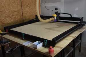
We built the 1500mm x 1500mm version of the WorkBee CNC router, which is based on the Openbuilds OX. It can currently cut sheet material of up to 50 mm thickness on a work area of approximately 1250 × 1250 mm. The surfaced (plangefräste) spoilboard area is 1260 × 1160 (x × y) mm.
Our plans for further improving it up can be found in our "WorkBee CNC" github project - maybe you would like to help?
Router
The router mounted to it is a Dewalt D26200 (GB; known outside Europe as DWP611). You need to consider the sizes of its collets (Spannzangen) when buying your router bits.
- no-load speed: 16000 - 27000 rpm
- max cutter diameter: 30 mm
- available collet diameters:
- 6 mm
- 8 mm
- 1/4 inch (6.35 mm)
- 1/8 inch (3.175 mm)
The collets of the DW613, DW620 and DW621 also fit the router and are easier to get in Germany than the original ones.
Spoilboard
Ooznest recommends a 6mm spoiler board, our first one is 20mm thick. It is mounted to the frame using 4 drop-in T-slot nuts. Cutting into the boards will make it uneven, from time to time it is neccessary to surface the spoiler board again.
The total size of the spoilboard is currently 1445 × 1370 mm.
When there is time, we would like to drill workholding holes into the spoilboard.
Electrics
(partially outdated - no dedicated CNC room since 2020!)
The spindle and the CNC controller (CNC xPro v3) + motors are hooked up to an electrical box on the left wall. You'll find a switch and an outlet for the spindle there. In case of an emergency the whole box can be shut off via one of the two emergency stops (inside the CNC room and on the outside above the access control). Everything except the Raspberry Pi will be turned off in that case.
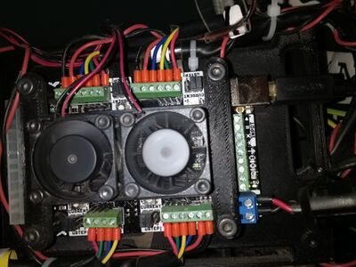
The wiring of the CNC Controller board is as follows:

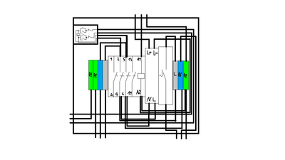
The wiring of the electrical box is as follows:

Dust Extraction
We have added a cyclone dust separator between the shop vac and the CNC router itself. Thereby, the bulk of the shavings and dust should be collected in an easily emptied box rather than the shop vac's bag.
The part that attaches the dust extraction hose to the router is called a "dust shoe". We are currently using this one designed by Patrick. The next version should ideally fit the dust extraction hose without an adapter and include a kind of transparent, flexible "skirt" to optimize the airflow.
Other interesting designs:
Workflow
This is just an overview and does NOT replace the personal introduction!
- create the tool paths in a suitable CAM software (e.g. Fusion 360)
- secure your workpiece on the machine's bed
- insert the appropriate collet & bit as defined in your tool paths
- turn the positioning motors on, home the machine and define the workpiece origin
- put on personal protection and turn the spindle on
- send the tool paths to the router in real time via the serial interface (USB)
- options can be found under "G-Code Senders"