WorkBee: Difference between revisions
Updating for post-rebuild processes |
added process documentation (tutorial) |
||
| Line 99: | Line 99: | ||
# Once the Machine has homed, turn on the spindle & vac on the control panel (only works after homing) | # Once the Machine has homed, turn on the spindle & vac on the control panel (only works after homing) | ||
# Be ready to hit the Emergency Stop in case SHTF. Your Program is running! | # Be ready to hit the Emergency Stop in case SHTF. Your Program is running! | ||
<span id="workbee-cnc-wiki-docs"></span> | |||
== Using the WorkBee CNC == | |||
This Section explains how to use the Machine to create parts. | |||
<span id="general-machine-operation"></span> | |||
== General Machine Operation == | |||
Interfacing with the WorkBee CNC has changed significantly after the 2024 rebuild. This section will explain its operation. | |||
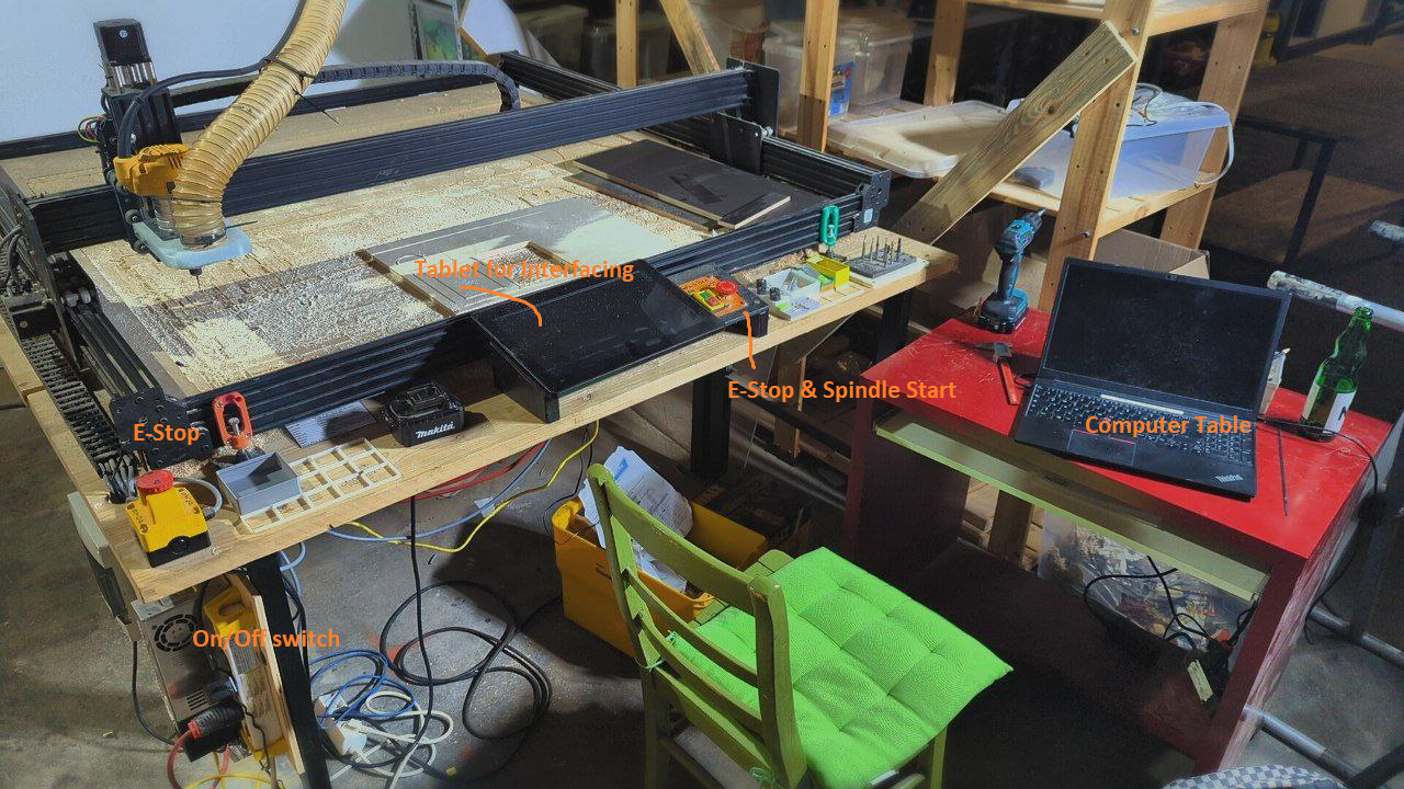
'''The machine:''' [[File:workbee-overview-labeled.png|480]] | |||
To start the Machine, the Electronics Panel on the left have a power strip (Mehrfachstecker) with a toggle switch. This is the main on/off switch. | |||
After starting, ensure both E-Stops are not pressed. The machine will start up, and you can open the Web Interface on the Tablet, PC or any other device. | |||
<span id="web-interface"></span> | |||
=== Web Interface === | |||
The WorkBee CNC is controlled via a Web Interface accessible through the CoMakingSpace network. On any connected device, visit <code>http://comakingcnc.fritz.box/</code> ([http://comakingcnc.fritz.box/ link]) or <code>10.2.0.3</code> to control the machine and upload jobs. | |||
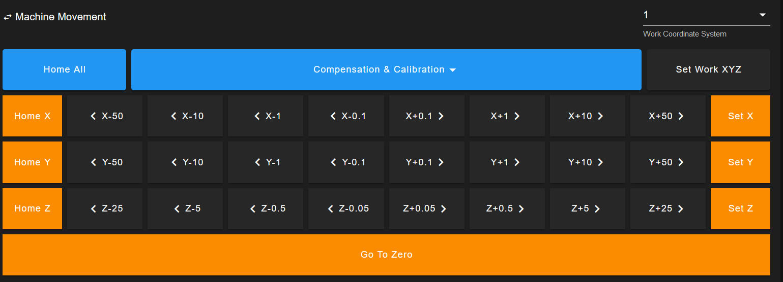
To start milling, you begin by inserting an endmill, homing the machine, and jogging the machine XY over your workpiece origin (usually the left-front corner). Then, slowly lower down until the tip of the endmill touches the workpiece. This is your workpiece zero point. Save this point by clicking on ''Set Work XYZ''. All this is done through ''Machine Movement'' on the Dashboard of the Web Interface: | |||
<div class="figure"> | |||
[[File:workbee-webinterface-jog.png|520]] | |||
</div> | |||
Then, upload your job to the machine, either on the top right of the Web Interface or through the ''Jobs'' tab. | |||
<span id="starting-a-job"></span> | |||
=== Starting a job === | |||
When starting a milling job, make sure the workpiece is secured well and you are wearing proper PPE. Next, start your job via the Web Interface. The machine will home. Then, after homing, you can start the spindle with the button on the front panel interface. This button will not work before homing or if no job is running to ensure someone is present at the start of any operation. | |||
Sit back, relax, and keep an eye out in case you need to use the E-Stop - the machine will now start making your parts. | |||
<span id="fusion-360-process-for-contour-machining"></span> | |||
== Fusion 360 Process for Contour Machining == | |||
The following section will walk you through setting up a contour milling operation in Fusion 360 for the WorkBee CNC. You will start with a New Fusion 360 Document and end up with a G-Code file ready to upload to the machine. | |||
For further information and the explanation for each step, consult the [https://help.autodesk.com/view/fusion360/ENU/?guid=GUID75B6821B-DE26-4E3B-AF10-4A54131CD9E4 Fusion 360 Documentation]. | |||
'''Before you get started, make sure you have properly imported the [https://github.com/comakingspace/WorkBee/tree/master latest version] of the machine definition and postprocessor into Fusion 360.''' | |||
<span id="prepare"></span> | |||
=== Prepare === | |||
To get started, you will need to create the 2D geometry you’d like to mill out. For testing, a simple hexagon is a good starting point. Extrude it by the material thickness you plan to machine. | |||
Then, in the top left corner of Fusion 360, switch from the “Design” workspace to the “'''Manufacture'''” workspace. This is where you’ll define your toolpaths and machine settings. | |||
<span id="create-your-milling-tool"></span> | |||
=== Create your Milling Tool === | |||
Take Measurements of your tool for dimensions using a caliper (Messschieber) and populate the values accordingly. | |||
The following cutting data is a recommended starting point for a 1/8” (3.175mm) 2-flute flat nose endmill cutting plywood. Tweak these values as you gain experience: | |||
* '''Spindle Speed (Drehzahl):''' 16,000 RPM | |||
* '''Cutting Feedrate (Schnittvorschub):''' 1000 mm/min | |||
* '''Helix Feedrate (Helixvorschub):''' 500 mm/min | |||
* '''Plunge Feedrate (Eintauchvorschub):''' 500 mm/min | |||
* '''Coolant:''' DISABLE (To prevent errors, the WorkBee doesn’t have a coolant system) | |||
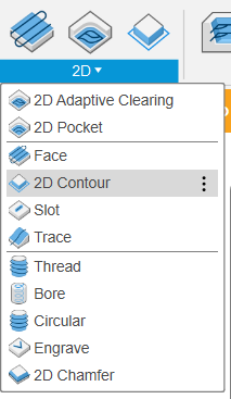
Now create a new 2D Contour operation by clicking 2D > 2D Contour. | |||
[[File:workbee-tutorial-2d-contour.png]] | |||
<span id="set-up-your-workpiece"></span> | |||
=== Set up your Workpiece === | |||
* Stock Box: | |||
** Set to '''Relative''' | |||
** 5 mm offset | |||
* Set Work Coordinate System | |||
** '''Stock Box Position:''' Select the Front-Left-Top Corner | |||
<span id="set-up-2d-contour-operation"></span> | |||
=== Set up 2D contour operation === | |||
'''Tab 1: Tool''' - Select the appropriate Tool - Ensure the cut parameters are sane and have been properly inherited from the tool | |||
'''Tab 2: Geometry''' - Select the 2D contour you want to machine (the bottom edge of your design). - Enable tabs - '''Tab Shape:''' Triangle - Tab dimensions example: - 6 mm width - 3 mm height - 30 mm Distance | |||
'''Tab 3: Heights''' - leave as is | |||
'''Tab 4: Passes''' - Sideways Compensation: Right (Rechtsfräsen) - '''OPTIONAL: Preserve order''' Check this box if you have nested features (cutouts within cutouts) to maintain the cutting order. - '''OPTIONAL: Smoothing Filter''' Enable for smaller file sizes | |||
'''Tab 5: Multi-Axis''' - leave as is | |||
Tab 6: Linking - '''Lead-In:''' Deactivate - '''Lead-Out:''' Deactivate - '''Ramp:''' Enable - '''Maximum Ramp Stepdown:''' Start with 3-6 mm and adjust based on endmill strength, desired cut quality, and material thickness | |||
'''Confirm the Operation with OK. Fusion 360 will now display a preview of the operation.''' | |||
<span id="simulate-to-check-export"></span> | |||
=== Simulate to check & Export === | |||
<div class="figure"> | |||
[[File:workbee-tutorial-export.png|420]] | |||
</div> | |||
* Use the “Simulate” tool to check you haven’t missed anything | |||
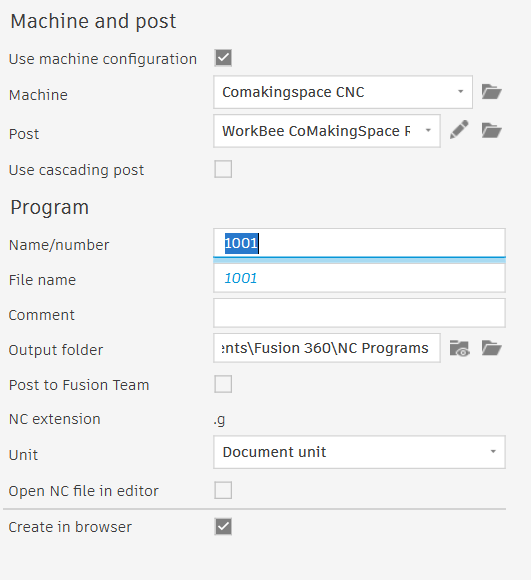
* At the top of the Fusion 360 Interface, click Post-Process | |||
* Check Use Machine Configuration (“Maschinenkonfiguration verwenden”) | |||
** Select Machine: “Comakingspace CNC” | |||
** Check Post-Processor: “WorkBee CoMakingSpace RRF” | |||
* Export | |||
You now have a G-Code file to upload to the CNC via its web interface! | |||
<span id="organization-around-the-machine"></span> | |||
== Organization around the Machine == | |||
Around the machine, there are plenty of ways to keep all tooling organized. These are for '''public''' things. Anything here is free to use for anyone, so leave your leftovers and take what you can use! | |||
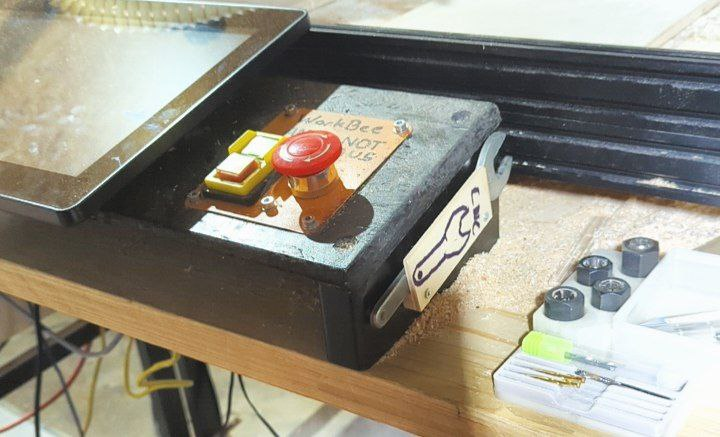
As with all other tools, please leave the CNC more organized than you found it. For example, the collet wrench should always return to its intended place: | |||
<div class="figure"> | |||
[[File:workbee-wrench.png|400]] | |||
</div> | |||
<span id="gridfinity"></span> | |||
=== Gridfinity === | |||
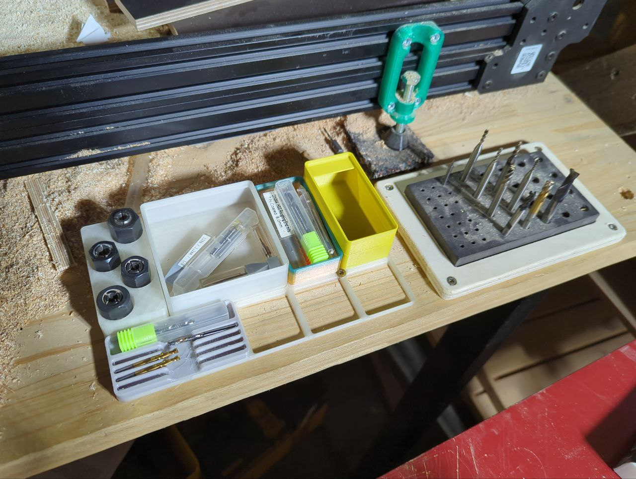
In front of the machine, at the table, there are [https://gridfinity.xyz/ Gridfinity] baseplates: | |||
<div class="figure"> | |||
[[File:workbee-gridfinity.png|400]] | |||
</div> | |||
'''Gridfinity''' is a 3D Printed organization system based on a 42mm grid. The bins in front of the machine are meant to be freely used, labeled and expanded upon. You can find additional bins to 3D Print on sites like [https://www.thingiverse.com/ Thingiverse], [https://www.printables.com/ Printables] and [https://thangs.com/?sort=trending Thangs]. For example, if we add more collets in the future, re-print the [https://www.printables.com/model/989475-gridfinity-dewalt-collet-holder collet holder]. | |||
<span id="pegboard"></span> | |||
=== Pegboard === | |||
On the wall left of the machine, there is a pegboard system for storing the larger items such as dust shoes. It is a '''Küpper''', also known as “Euro” style pegboard based on a 15 mm grid of 4.5 mm holes. Just as with Gridfinity above, the usual sites offer various ready-made 3D models of hooks and holders to print yourself, and there’s always the option to just buy more hooks from Küpper at [https://www.bauhaus.info/werkzeugwaende/kuepper-lochwandhaken-set-72000/p/11142266 Bauhaus] or [https://www.amazon.de/s?k=k%C3%BCpper+lochwand Amazon]. | |||
<br clear=all> | <br clear=all> | ||
Revision as of 21:47, 10 September 2024
WorkBee
| MachineInfoBox Ooznest WorkBee CNC | |
|---|---|
| |
| Synonyms: | DE: CNC-Fräse, CNC-Plattenfräse, Portalfräsmaschine |
| Type: | CNC Router |
| Material: | wood |
| Used with: | 6 mm, 8 mm, 1/4" or 1/8" end mills; some kinds of router bits |
| Location: | CNC Area |
| Access Requirements: | CNC Router Introduction |
| Status: | Working |
| Software: | LaserWeb, Fusion360, see G-Code Sender |
| Firmware: | grbl |
| Manual: | product page, click "documentation" tab |
| Tutors: | NitramLegov Pakue Johannes Luzian Leo Maker-Joe |
| Similar (More or Less): | router, CNC mill |
Currently defective due to a buggy/broken controller board! See Issue #307
We have a 1500mm x 1500mm version of the WorkBee CNC router, which is based on the Openbuilds OX. It can currently cut sheet material of up to 50 mm thickness on a work area of approximately 1250 × 1250 mm. The surfaced (plangefräste) spoilboard area is 1260 × 1160 (x × y) mm.
Our plans for further improving it up can be found in our "WorkBee CNC" github project - maybe you would like to help.
Fusion 360 Setup
To use the router in Fusion 360, make sure you add the latest machine definition and post-processor to Fusion 360.
You can find the newest version of these required files here. Feel free to submit improvements.
Router
The router mounted to it is a Dewalt D26200 (GB; known outside Europe as DWP611). You need to consider the sizes of its collets (Spannzangen) when buying your router bits.
- no-load speed: 16000 - 27000 rpm
- max cutter diameter: 30 mm
- available collet diameters:
- 8 mm
- 6 mm
- 1/4 inch (6.35 mm)
- 1/8 inch (3.175 mm)
The collets of the DW613, DW620 and DW621 also fit the router and are easier to get in Germany than the original ones.
| Dial Setting | Approx. RPM |
|---|---|
| 1 | 16000 |
| 2 | 18200 |
| 3 | 20400 |
| 4 | 22600 |
| 5 | 24800 |
| 6 | 27000 |
Spoilboard
Ooznest recommends a 6mm spoiler board, our first one is 20mm thick. It is mounted to the frame using 4 drop-in T-slot nuts. Cutting into the boards will make it uneven, from time to time it is neccessary to surface the spoiler board again.
The total size of the spoilboard is currently 1445 × 1370 mm.
When there is time, we would like to drill workholding holes into the spoilboard.
Electrics
The Machine received a full electrical overhaul in the first half of 2024, here are its current electrical specifications:
- Duet 3 6HC+ Mainboard running RepRapFirmware
- Web- and touch interface
- MT-2303HS280AW 2.8A NEMA23 Stepper Motors
- Dewalt D26200 Router
Dust Extraction
The Workbee Vacuum automatically turns on with the spindle. We have added a cyclone dust separator before the shop vac so the bulk of the chips should be collected in an easily emptied box rather than the shop vac's bag.
The part that attaches the dust extraction hose to the router is called a "dust shoe". We are currently using this one designed by Patrick. The next version should ideally fit the dust extraction hose without an adapter and include a kind of transparent, flexible "skirt" to optimize the airflow.
Other interesting designs:
Workflow
This is just an overview and does NOT replace the personal introduction!
- create the tool paths in a suitable CAM software (e.g. Fusion 360)
- secure your workpiece on the machine's bed
- insert the appropriate collet & bit as defined in your tool paths
- home the machine, jog to your workpiece origin and zero your work coordinates
- Upload your generated G-Code
- put on personal protection
- Run your Program
- Once the Machine has homed, turn on the spindle & vac on the control panel (only works after homing)
- Be ready to hit the Emergency Stop in case SHTF. Your Program is running!
Using the WorkBee CNC
This Section explains how to use the Machine to create parts.
General Machine Operation
Interfacing with the WorkBee CNC has changed significantly after the 2024 rebuild. This section will explain its operation.
To start the Machine, the Electronics Panel on the left have a power strip (Mehrfachstecker) with a toggle switch. This is the main on/off switch.
After starting, ensure both E-Stops are not pressed. The machine will start up, and you can open the Web Interface on the Tablet, PC or any other device.
Web Interface
The WorkBee CNC is controlled via a Web Interface accessible through the CoMakingSpace network. On any connected device, visit http://comakingcnc.fritz.box/ (link) or 10.2.0.3 to control the machine and upload jobs.
To start milling, you begin by inserting an endmill, homing the machine, and jogging the machine XY over your workpiece origin (usually the left-front corner). Then, slowly lower down until the tip of the endmill touches the workpiece. This is your workpiece zero point. Save this point by clicking on Set Work XYZ. All this is done through Machine Movement on the Dashboard of the Web Interface:
Then, upload your job to the machine, either on the top right of the Web Interface or through the Jobs tab.
Starting a job
When starting a milling job, make sure the workpiece is secured well and you are wearing proper PPE. Next, start your job via the Web Interface. The machine will home. Then, after homing, you can start the spindle with the button on the front panel interface. This button will not work before homing or if no job is running to ensure someone is present at the start of any operation.
Sit back, relax, and keep an eye out in case you need to use the E-Stop - the machine will now start making your parts.
Fusion 360 Process for Contour Machining
The following section will walk you through setting up a contour milling operation in Fusion 360 for the WorkBee CNC. You will start with a New Fusion 360 Document and end up with a G-Code file ready to upload to the machine.
For further information and the explanation for each step, consult the Fusion 360 Documentation.
Before you get started, make sure you have properly imported the latest version of the machine definition and postprocessor into Fusion 360.
Prepare
To get started, you will need to create the 2D geometry you’d like to mill out. For testing, a simple hexagon is a good starting point. Extrude it by the material thickness you plan to machine.
Then, in the top left corner of Fusion 360, switch from the “Design” workspace to the “Manufacture” workspace. This is where you’ll define your toolpaths and machine settings.
Create your Milling Tool
Take Measurements of your tool for dimensions using a caliper (Messschieber) and populate the values accordingly.
The following cutting data is a recommended starting point for a 1/8” (3.175mm) 2-flute flat nose endmill cutting plywood. Tweak these values as you gain experience:
- Spindle Speed (Drehzahl): 16,000 RPM
- Cutting Feedrate (Schnittvorschub): 1000 mm/min
- Helix Feedrate (Helixvorschub): 500 mm/min
- Plunge Feedrate (Eintauchvorschub): 500 mm/min
- Coolant: DISABLE (To prevent errors, the WorkBee doesn’t have a coolant system)
Now create a new 2D Contour operation by clicking 2D > 2D Contour.
Set up your Workpiece
- Stock Box:
- Set to Relative
- 5 mm offset
- Set Work Coordinate System
- Stock Box Position: Select the Front-Left-Top Corner
Set up 2D contour operation
Tab 1: Tool - Select the appropriate Tool - Ensure the cut parameters are sane and have been properly inherited from the tool
Tab 2: Geometry - Select the 2D contour you want to machine (the bottom edge of your design). - Enable tabs - Tab Shape: Triangle - Tab dimensions example: - 6 mm width - 3 mm height - 30 mm Distance
Tab 3: Heights - leave as is
Tab 4: Passes - Sideways Compensation: Right (Rechtsfräsen) - OPTIONAL: Preserve order Check this box if you have nested features (cutouts within cutouts) to maintain the cutting order. - OPTIONAL: Smoothing Filter Enable for smaller file sizes
Tab 5: Multi-Axis - leave as is
Tab 6: Linking - Lead-In: Deactivate - Lead-Out: Deactivate - Ramp: Enable - Maximum Ramp Stepdown: Start with 3-6 mm and adjust based on endmill strength, desired cut quality, and material thickness
Confirm the Operation with OK. Fusion 360 will now display a preview of the operation.
Simulate to check & Export
- Use the “Simulate” tool to check you haven’t missed anything
- At the top of the Fusion 360 Interface, click Post-Process
- Check Use Machine Configuration (“Maschinenkonfiguration verwenden”)
- Select Machine: “Comakingspace CNC”
- Check Post-Processor: “WorkBee CoMakingSpace RRF”
- Export
You now have a G-Code file to upload to the CNC via its web interface!
Organization around the Machine
Around the machine, there are plenty of ways to keep all tooling organized. These are for public things. Anything here is free to use for anyone, so leave your leftovers and take what you can use!
As with all other tools, please leave the CNC more organized than you found it. For example, the collet wrench should always return to its intended place:
Gridfinity
In front of the machine, at the table, there are Gridfinity baseplates:
Gridfinity is a 3D Printed organization system based on a 42mm grid. The bins in front of the machine are meant to be freely used, labeled and expanded upon. You can find additional bins to 3D Print on sites like Thingiverse, Printables and Thangs. For example, if we add more collets in the future, re-print the collet holder.
Pegboard
On the wall left of the machine, there is a pegboard system for storing the larger items such as dust shoes. It is a Küpper, also known as “Euro” style pegboard based on a 15 mm grid of 4.5 mm holes. Just as with Gridfinity above, the usual sites offer various ready-made 3D models of hooks and holders to print yourself, and there’s always the option to just buy more hooks from Küpper at Bauhaus or Amazon.
