LaserCut 5.3: Difference between revisions
→Setting the Worktable Size: added missing values - is there more to change than "Range"? |
No edit summary |
||
| Line 156: | Line 156: | ||
===Simulating your job=== | ===Simulating your job=== | ||
[[File:Simulate_Button_2.png]] or [[File:Simulate_Button.png]] | |||
===Estimating Work Time=== | ===Estimating Work Time=== | ||
[[File:Estimate_Work_Time_Button.png]] | |||
Revision as of 20:45, 1 July 2022
| SoftwareInfoBox LaserCut 5.3 or Lasercut 5.3 | |
|---|---|
| |
| Type: | laser cutter driver/CAM |
| Platform: | Windows (XP, 7, 8, 10 [1]) |
| License: | |
| Source: | |
| Input Formats: | PLT, AI, DXF, DST, BMP, NC, JPG, GIF, PNG, TIF, TGA, PCX |
| Output Formats: | MOL |
| Users: | Martin |
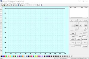
Lasercut 5.3 is required to prepare a design file for our laser cutter. Its drawing functions are apparently quite terrible, so pretty much all users in forums etc. recommend to only use it for the very last steps!
If you are familiar with "our" previous laser cutter (the loaned Epilog Zing), this software will pretty much take over what you used to do with Visicut.
LaserCut 5.3 is installed on a dedicated PC, which is located next to the laser cutter itself.
This page needs more information as soon as we gather the necessary experience!
starting points:
- summary by our laser's retailer
- Guide by the Bristol Hackspace
Installation
We got a copy of LaserCut 5.3 from HPC Laser. You can get it from the orange USB drive located next to the laser cutter. However, the version we got does only work with the "soft dog" USB dongle, which will be attached permanently to the dedicated PC.
In order to prepare files on your own computer, you can install the software from another source. Most sources include an executable called "Lasercut53_Demo.exe" which can be used without the dongle but cannot operate the machine itself. The demo version also does not want you to save or open project files, but there are workarounds:
- saving is reportedly offered when closing the program
- opening of a finished project is best done with our full version at the Space, but also possible after some "terrible" exporting/re-importing [2]
In case you plan to do these, please make sure that you replace your syscfg.ini with the one shipped with our laser (can be found on the mentioned USB drive).
Installation notes:
- The software only natively works on Windows. Try Wine or other methods at your own risk, but be aware it's 32-bit software
- The software must be installed in C:\LaserCut53 in order to work properly. There is a parameter in syscfg.ini which indicates the installation path. Changing it might get it to work from other locations as well but is untested. Try at your own risk.
Setup
Setting the Worktable Size
The first thing to do after installation is to check for the correct worktable size. Our laser has a size of 90x60 cm. Please ensure your worktable is set up correctly.
If it is not, you can change it by navigating to File-->Machine Options (or pressing Ctrl+J).
In the new window, please navigate to "Worktable" and apply the following settings:
- X Axis [Range] 900.0
- Y Axis [Range] 600.0
When clicking "Save", it will most likely ask you for a password. Just hit "OK".
Basic Usage
Zoom to all objects
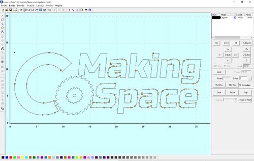
Sometimes you need to ensure that all your objects are visible on the screen. To do so, please use "Zoom to all objects"
Note: You can use this tool in order to ensure all your objects are on the worktable. Objects outside the worktable will result in a soft stop of the laser.
Zoom to table
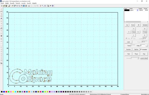
This tool is particulary helpful in case you zoomed in or out of your worktable and want to see the entire worktable centralized on your screen:
Preparing a Job
Import your file
The first thing you need to do is to import your drawing. You can do so by navigating to File-->Import or by pressing Crtl+I. The following file formats are supported:
- PLT
- DXF
- Fusion 360: export the file. Do not just "save as".
- Inkscape: reportedly, the checkboxes "Use ROBO-Master type of spline output" and "Use LWPOLYLINE type of line output" need to be off when saving as DXF for LaserCut 5.3 [3]
- AI (Adobe Illustrator)
- JPG
- GIF
- PNG
- BMP
- TIF
- DST
- NC
- TGA
- PCX
Preparing the Cut Paths
Once your file is imported, you will see the preview on the screen. The following tools might be handy when preparing your cut paths:
Unite Lines
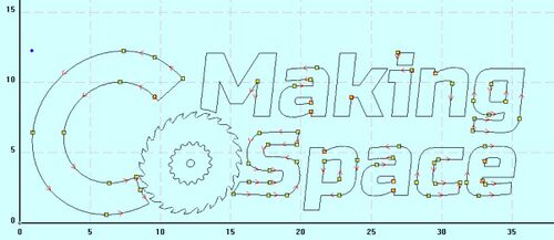
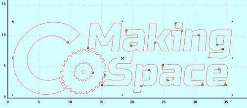
In case you just start your job without any further tuning, you might recognize that the laser follows an odd order of steps to cut your paths.
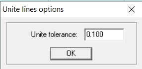
In order to streamline this, please select the paths of your model and navigate to Tools-->Unite Lines.
Note: The default value of 0.100 as the unite tolerance is usually a pretty good value to recognize lines belonging together.
Output Order
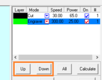
You often want to engrave before cutting as the cut parts can fall out of focus when they are separated from the rest of the material.
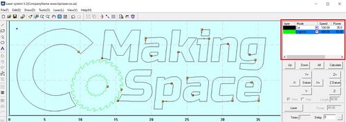
easy way: select a "layer" in the list on the right and move it around with the "Up" or "Down" buttons (top is done first, bottom last)
You can also control the order of the cuts by navigating to Tools-->Output Order: In the new window, you will get a list of output layers, which you can put into the desired order by selecting them on the left and moving them to the right side of the window.
If you are not sure which number corresponds to which cutting path, please not that you can select lines while having the output order window open.
Setting the entry point
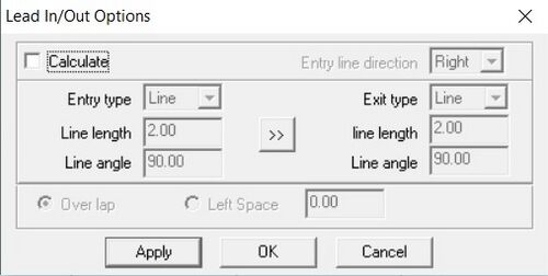
On each path you can select the entry point the laser will use by using the "Define cut route" tool. You can find this in the menu Laser-->Define cut route or in the menu bar:
Hint: If you press space when using this tool, a new window will open allowing you to edit some expert settings:
Copy
Especially when mass processing something, you might want to copy your drawing multiple times. LaserCut offers a few different options to do so:
- Mark the paths, use CRTL-C and CTRL-V, then move the new paths
- Mark the paths, navigate to Draw-->Copies
This will create actual copies of your object in an array which you can define. After the copies have been created, they are independent of each other and can be modified and moved seperately. - Mark the paths, navigate to Laser-->Array output options
This will allow you to laser your paths multiple times. Please note that the copies are not independent of each other and can only be moved together. Also, the same settings apply for all of them.
Selecting the laser mode
| Mode | Explanation |
|---|---|
| Cut | Cuts your material by following the defined vectors. You can also use this for vector engraving by lowering the power. |
| Engrave | Engraves the shapes of your drawing into your material (similar to a printer). Use this to engrave pictures. On vector drawings, this will engrave |
| Grade Engrave | Grade engraving will tell the laser to bevel the corners of your engraving. This should increase readability of letters for example. |
| Hole | This setting is similar to cutting. It will follow the defined lines, but will only make little dots (holes) into your material. |
| Pen Cut | This setting seems to crash LaserCut 5.3 and is not documented in the manual. |
Setting Power and Speed
You can set the power and speed for each layer seperately in the Control Panel:
Here you can select the desired mode by using the correspondent drop done menu.
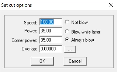
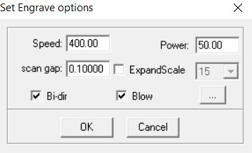
Double-clicking on a layer will open the speed settings for the specific layer. Please note that the options for cutting and engraving differ from each other:
Please put special focus on the "Corner Power". Usually you want to put this to the same power as your regular power.
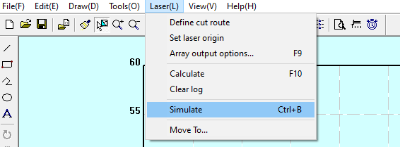
Simulating your job
Estimating Work Time
Controlling the Laser
ADD IMAGE: Control Panel
Homing
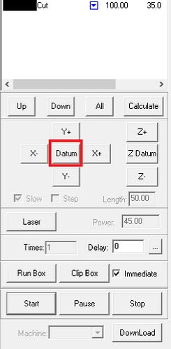
In Order to Home the Laser, please press "Datum". (Fun Fact: "Datum" is not a strange translation, but actually the correct term (see Wiktionary):
Homing the Laser will cause it to move into the upper right corner. Please always home the laser before you use it.
NOTE: You can also Home the Laser by pressing "Datum" on the control panel of the Laser itself.
Moving the Laser
You will need to move the Laser to it´s correct starting position, which you decided on when you prepared your job.
In order to do so, please use the X+/- and Y+/- Buttens in the Control Panel.
Please Note that you cannot control the Z-Height from within LaserCut. You will need to set the proper height on the machine itself!
Uploading your Job
Once you are done with all preperation steps, you need to put your job on the machine. In order to do so, please press the "DownLoad" Button in the control panel. This will open a window called "Stand-alone file manager":
ADD IMAGE: Stand alone file manager
In here, you can select your desired job and press "Download file". You can also just hit "Download current" to put the latest job onto the machine.
If - for whatever reason - you want to store this exact setup and machine data, you can export the data by pressing "export file". This will allow you to save it as a .mol file.
Starting and Stopping the Job
You can start the job in Lasercut or on the machine.
In order to start it from Lasercut, please use the "Start" Button on the control panel. You can also pause and stop the job by using the correspondent buttons.
Please Note that it is recommended to always control the job from the laser itself!

