Project:Raspberry Pi Smart Light Switch Shield: Difference between revisions
Fleshing out the pages content |
Added images. |
||
| Line 1: | Line 1: | ||
{{ProjectInfoBox | {{ProjectInfoBox | ||
|project title=Raspberry Pi Smart Light Switch Shield | |project title=Raspberry Pi Smart Light Switch Shield | ||
|image= | |image=schematic_main.png | ||
|status=In progress | |status=In progress | ||
|date=January 2021 | |date=January 2021 | ||
| Line 19: | Line 19: | ||
<br clear=all> | <br clear=all> | ||
== Circuit Design == | == Circuit Design == | ||
[[File: | [[File:Output stages.png|thumb|professional circuit design]] | ||
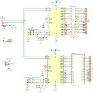
The design was created using the free and open-source software [[KiCad]]. After a long evening of shittalking in a video conference {{NL}} somehow convinced [[User:Jonah|Jonah]] do create the schematic for a shield that would allow a [[Raspberry Pi]] to control the impulse switches in our electrical cabinet. Even more suprisingly, [[User:Leo|Leo]] promised to create a PCB from this schematic despite having virtually no experience in creating [[PCB|PCBs]]. All in all, a perfect set of circumstances for a successful [[Projects|project]]. | The design was created using the free and open-source software [[KiCad]]. After a long evening of shittalking in a video conference {{NL}} somehow convinced [[User:Jonah|Jonah]] do create the schematic for a shield that would allow a [[Raspberry Pi]] to control the impulse switches in our electrical cabinet. Even more suprisingly, [[User:Leo|Leo]] promised to create a PCB from this schematic despite having virtually no experience in creating [[PCB|PCBs]]. All in all, a perfect set of circumstances for a successful [[Projects|project]]. | ||
== Requirements == | == Requirements == | ||
A good [[Projects|project]] starts out with properly defined requirements. This Shield must fit a [[Raspberry Pi|Raspberry P]]<nowiki/>i 3B or 4B and allow for switching impulse switches via MCP23017 IO expanders. For safety reasons the Pi and its IO expanders should be protected using Optocouplers | A good [[Projects|project]] starts out with properly defined requirements. This Shield must fit a [[Raspberry Pi|Raspberry P]]<nowiki/>i 3B or 4B and allow for switching impulse switches via MCP23017 IO expanders. For safety reasons the Pi and its IO expanders should be protected using Optocouplers, connecting 24V to a 3.3V rail is known to cause premature failure in many electrical components. | ||
Further requirements given by project members other than {{NL}} where a demand for "dope-ass silkscreen artwork" and debug LEDs for convenient | Further requirements given by project members other than {{NL}} where a demand for "dope-ass silkscreen artwork" and debug LEDs for convenient debugging. | ||
== Design Process == | == Design Process == | ||
Revision as of 21:39, 4 January 2021
| ProjectInfoBox Raspberry Pi Smart Light Switch Shield | |
|---|---|

| |
| Status: | In progress |
| Release Date: | January 2021 |
| Initiator: | Martin's constant bitching |
| Team: | Jonah, Leo, Johannes, Martin |
| Materials Used: | Raspberry Pi 3B, Custom-ordered PCBs |
| Tools Used: | Mouse and Keyboard |
| Software Used: | KiCad |
| Approx. Cost: | To be determined |
Martins constant bitching has spawned a project with the goal of controlling the lights of the space via a Raspberry Pi running HomeAssistant.
This page documents the design process of the PCB that connects the Pi with its software to the electrical cabinet with its lights and electricity.
Circuit Design

The design was created using the free and open-source software KiCad. After a long evening of shittalking in a video conference Martin somehow convinced Jonah do create the schematic for a shield that would allow a Raspberry Pi to control the impulse switches in our electrical cabinet. Even more suprisingly, Leo promised to create a PCB from this schematic despite having virtually no experience in creating PCBs. All in all, a perfect set of circumstances for a successful project.
Requirements
A good project starts out with properly defined requirements. This Shield must fit a Raspberry Pi 3B or 4B and allow for switching impulse switches via MCP23017 IO expanders. For safety reasons the Pi and its IO expanders should be protected using Optocouplers, connecting 24V to a 3.3V rail is known to cause premature failure in many electrical components.
Further requirements given by project members other than Martin where a demand for "dope-ass silkscreen artwork" and debug LEDs for convenient debugging.
Design Process
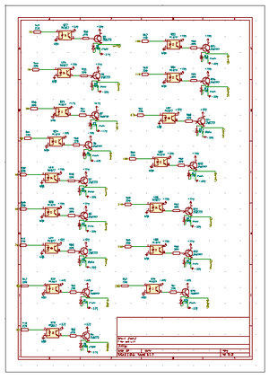
The Schematic by Jonah was plagued with terrible design choices. Instead of designing the output stage once, and dynamically linking to that one output stage, he created 16 copies of the output stage for all 16 pins. This is bad circuit design practice and should be avoided. And to top it of, he built the input stages the same way. As a result the KiCad project contains 15 redundant copies of both the input and output stage.
Another terrible design choice was using components with footprints that aren't included in the KiCad standard library and giving someone with close to no experience in designing PCBs the talk of creating them, but since we haven't ordered the PCBs I can't back up this statement yet.