Project:Microfluidics: Difference between revisions
m InfoBox title capitalization |
|||
| (6 intermediate revisions by 2 users not shown) | |||
| Line 1: | Line 1: | ||
{{ProjectInfoBox | {{ProjectInfoBox | ||
|project title= DIY Microfluidics | |project title= DIY Microfluidics Devices | ||
|image= Microfluidics thumbnail.jpg | |image= Microfluidics thumbnail.jpg | ||
|date = Q1 2019 | |date = Q1 2019 | ||
|status= in | |status= in development | ||
|initiator= [http://www.biotop-heidelberg.de BIOTOP Community Lab e.V.] | |initiator= [http://www.biotop-heidelberg.de BIOTOP Community Lab e.V.] | ||
|team= Patrick & [[User:Yunus|Yunus]] | |team= [[User:P|Patrick]] & [[User:Yunus|Yunus]] | ||
|materials=Acrylic | |materials=[[Acrylic Glass]], 3M Double Sided Tape | ||
|tools= Laser Cutter, Biotop Lab | |tools=[[Laser Cutter]], Biotop Lab | ||
|software= Affinity Designer, VisiCut | |software=[[Affinity Designer]], [[VisiCut]] | ||
|cost= | |cost= | ||
}} | }} | ||
Microfluidics deals with the behaviour, precise control and manipulation of fluids that are geometrically constrained to a small, typically sub-millimetre, scale at which capillary penetration governs mass transport. - Our goal is to develop custom DIY microfluidics chips (currently as a proof of concept), and perform lab-on-a-chip like experiments. | Microfluidics deals with the behaviour, precise control and manipulation of fluids that are geometrically constrained to a small, typically sub-millimetre, scale at which capillary penetration governs mass transport. - Our goal is to develop custom DIY microfluidics chips (currently as a proof of concept), and perform lab-on-a-chip like experiments. | ||
== Development of our own microfluidics devices == | == Development of our own microfluidics devices == | ||
=== | === Concept === | ||
== | == Version History == | ||
==== V 0 ==== | [[File: Microfluidics-progress.png|border|300px]] | ||
==== V 0 and V 1 ==== | |||
Version Zero was our first shot at microfluidics. We wanted to perform a simple proof-of-concept: Get liquid flowing from an input hole through a spiral to an output hole. | Version Zero was our first shot at microfluidics. We wanted to perform a simple proof-of-concept: Get liquid flowing from an input hole through a spiral to an output hole. | ||
The chip was made from three laser cut layers: A top acrylic glass plate with the input and output wholes, a middle layer made out of double sided 3M tape that included the actual channels, and finally a bottom layer. | The chip was made from three laser-cut layers: A top acrylic glass plate with the input and output wholes, a middle layer made out of double sided 3M tape that included the actual channels, and finally a bottom layer. | ||
With Version One we improved our channel smoothness and overall build quality. | |||
-> Images -> Laser Settings | -> Images -> Laser Settings | ||
==== V 2 - V 4 ==== | |||
==== V 2 | |||
==== V B02 ==== | ==== V B02 ==== | ||
Latest revision as of 22:02, 22 September 2022
| ProjectInfoBox DIY Microfluidics Devices | |
|---|---|

| |
| Status: | in development |
| Release Date: | Q1 2019 |
| Initiator: | BIOTOP Community Lab e.V. |
| Team: | Patrick & Yunus |
| Materials Used: | Acrylic Glass, 3M Double Sided Tape |
| Tools Used: | Laser Cutter, Biotop Lab |
| Software Used: | Affinity Designer, VisiCut |
Microfluidics deals with the behaviour, precise control and manipulation of fluids that are geometrically constrained to a small, typically sub-millimetre, scale at which capillary penetration governs mass transport. - Our goal is to develop custom DIY microfluidics chips (currently as a proof of concept), and perform lab-on-a-chip like experiments.
Development of our own microfluidics devices
Concept
Version History
V 0 and V 1
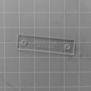
Version Zero was our first shot at microfluidics. We wanted to perform a simple proof-of-concept: Get liquid flowing from an input hole through a spiral to an output hole. The chip was made from three laser-cut layers: A top acrylic glass plate with the input and output wholes, a middle layer made out of double sided 3M tape that included the actual channels, and finally a bottom layer.
With Version One we improved our channel smoothness and overall build quality.
-> Images -> Laser Settings
V 2 - V 4
V B02
V B03
V B04
V B04-A V B04-B
