Project:Laptop Wall Mount
| ProjectInfoBox Laptop Wall Mount | |
|---|---|
| |
| Status: | successful prototype |
| Release Date: | Feb 2017 |
| Initiator: | Lukas |
| Team: | Manü, Patrick |
| Materials Used: | plywood, wood glue, ring screws, screws, scrap metal |
| Tools Used: | laser cutter, disc grinder, pruning saw |
| Software Used: | Fusion 360, Inkscape, VisiCut |
| Approx. Cost: | 5 € (mostly for the plywood) |
A while ago we started to develop a laser cut laptop wall mount. The design process, manufacturing, and further ideas for this handy piece of geek furniture will be documented here!
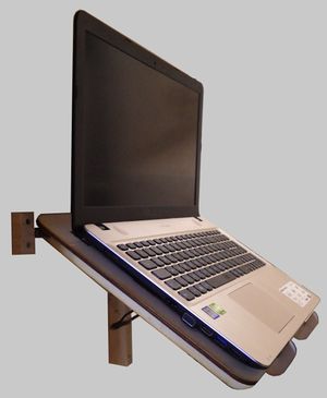
The assembly consists of a table, a wall mount for the hinging rod and a "leg" holding the table in position when desired.
Design Goals
The laptop mount was supposed to
- fold down when not in use to save space
- hold various sizes of laptops
- not block the sides where cables might insert
- keep the laptops from falling down...
Process

The Fusion 360 seminar was a good opportunity to start with the table portion as the attendees were learning the software on a similar project, a tabletop laptop stand.
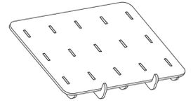
For stability, the strongest plywood thickness we had laser cut so far (6 mm) was incorporated into the design. The table is basically a flat sheet with 5 "ribs", two of which protrude over the surface in the front to keep the laptop from sliding off. In the back, the ribs are penetrated by a steel rod which will be mounted to a board on the wall with ring screws and some wooden stop blocks to keep that from sliding away, too.
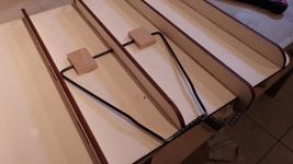
The table's "leg" was fashioned from a piece of thick wire (approx. 3 mm diameter) bent into a trapezoid shape and held together by a tightly wrapped thin wire where its ends overlap. This thicker and irregularly shaped section can slide into a grooved piece of scrap wood screwed to the wall plate. It hinges in grooves/holes in the central table rib and two additional parts that were sawn and glued to the underside of the table for more stability.
Gallery
- some steps along the way
-
design drawing in Fusion 360
-
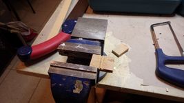
cutting a wooden "hinge"
-
aligning the leg to fold freely
-
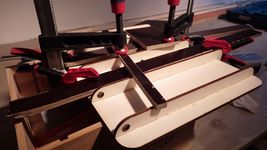
glue up utilizing some scrap wood to spread the pressure
-
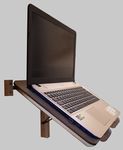
finished wall mount holding a laptop!
Further Plans
The non-table parts and the groove in the central rib were added by hand and are not yet included in the above design file.
Once a stable solution is found, the design could be redefined with parameters based solely on the desired table area, material thickness and dowel diameter to allow customized versions for any need. OpenSCAD (with some kind of svg generation workflow) could be used for that...
