Project:Aquarium Edge Illumination: Difference between revisions
m probably finished |
m Category:Lighting |
||
| Line 75: | Line 75: | ||
[[Category:3D Printing]] | [[Category:3D Printing]] | ||
[[Category:Electronics]] | [[Category:Electronics]] | ||
[[Category:Labware]] | [[Category:Labware]] | ||
[[Category:Lighting]] | |||
[[Category:Microcontrollers]] | |||
Latest revision as of 18:58, 3 September 2023
| ProjectInfoBox Aquarium Edge Illumination | |
|---|---|

| |
| Status: | probably finished |
| Release Date: | June 2018 |
| Initiator: | Lukas |
| Materials Used: | LED strips, Arduino UNO |
| Software Used: | Fusion 360 |
| Approx. Cost: | approx. 20 € (without the Arduino) |
For my PhD project, I needed to film fish in a small aquarium (5-8 L) from the side and the top.
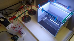
After some less succesful attempts, it seems the most even lighting that will not obstruct the top camera is a rectangle of LED strips along the top edge.
Initial Situation
Design Goals
- light intensity & angle controlled independently for each side
- electronics protected from the water
- controlled from at least 1 m away
Constraints
- LED strip: "YourLED" 40 LED/m daylight (6000 K)
- (somewhat) waterproof silicone cover
- analog control
- 3 mm thick
- 10.5 mm wide
- splittable every 7.5 cm
- aquarium: 4 mm thick glass, partially laid out with 3 mm thick rigid foam board (probably PVC)
- outside 26.5 × 18.9 × 23.1 cm
- inside (top) 25.6 × 18.2 × 22.5 cm
- ! protruding glass pieces (17 × 99 mm) at short sides 7.3 mm below the edge
Approach
I cut the LED strip into two 15 cm and two 22.5 cm pieces which were powered through separate MOSFETs that were controlled by an Arduino microcontroller. The holders for the strips were 3D printed and allowed angle adjustments. Electronic connections were protected by heatshrink. A control panel with dials for each strip's brightness would help with the setup process but was not a priority.
Make
3D Printing
The first prototype for the 3D printed holders sat on the glass very well but was of course not perfect yet and missing some important features. These will be improved in the next version:
lip to shield the top camera from direct lightwould reduce ease of printing - probably just a piece of electrical tape in the end- slightly wider slots (+0.2 mm) so the screws slide freely
- move "legs" to the edges so the LED strip's range of movement is increased and there is room for wing nuts "outside"
- longer slots on all parts
- deal with various design bugs in Fusion...
- make all sides "short" - corners are too crowded with parts for free adjustment and may also be over-lit otherwise
The large parts should be printed with the area that will hold the LED strip touching the print bed. This orientation is important - it was not chosen for strength, but optimum conditions for the adhesive backing of the LED strips. This is also the orientation with minimum overhangs so mistakes should be prevented by design.
Electronics

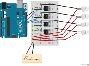
- prototyped with a breadboard & Arduino Uno
- suitable USB power supply would be 5V/500mA [1]
- other components: four IRF510 MOSFETs, four 10 kOhm resistors as pulldowns, four 150 mm LED strip sections & 12V/1.5A power supply
- wiring: pretty much according to Step 5 of "Intro to LED Strips" on Instructables.com
- PWM control:
analogWrite (pin, value)- accessing each LED strip's control pin (6 & 9-11) as "left", "right", "front", "back" in the code
- input only via uploading new values to the Arduino...
Programming
Just some very simple bits of Arduino code ;-)
Accessible via GitHub in case you're interested.
Visible flickering of lights in the video was addressed by increasing the PWM frequency as described here.
Bugs
- pulldown resistors (10 kOhm) didn't have any effect - does anyone have an idea why?
- it gets dark enough for the sake of this project, but still annoying that I can't actually turn the light off completely...
- Korbi suggested that the MOSFETs may have been damaged during installation and are therefore "leaking"
- possible causes: static, wrong multimeter use (should be at drain before gate), 12 V connected before Arduino?
- to verify: if there is really 0 V at the gate, it must be a leak and not a control issue; resistance drain-source should be OL