Project:Digital Holographic Miocroscope: Difference between revisions
upload project photo |
m linked users |
||
| (3 intermediate revisions by one other user not shown) | |||
| Line 4: | Line 4: | ||
|status=being built | |status=being built | ||
|date= | |date= | ||
|initiator=Patrick, Lennart | |initiator=[[User:P|Patrick]], [[User:Lennart|Lennart]] | ||
|team= | |team= | ||
|materials= | |materials= | ||
| Line 10: | Line 10: | ||
|software= | |software= | ||
|cost= | |cost= | ||
}} | }} | ||
=== Introduction === | |||
==== Holmos ==== | |||
This project is based on project Holmos (https://github.com/holmos-ipm) by Fraunhofer IPM. | |||
==== Digital Holographic Microscopy ==== | |||
Wikipedia https://en.wikipedia.org/wiki/Digital_holographic_microscopy | Wikipedia https://en.wikipedia.org/wiki/Digital_holographic_microscopy | ||
This file explains the constraints in optical adjustment https://github.com/holmos-ipm/holmos-hardware/blob/master/instructions/optics_design.md | |||
=== Assembly === | |||
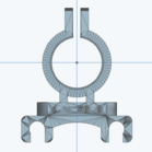
Mounts for the optical components can be printed from files provided in the project repo. These can then be axially moved on metal beams. A Raspberry Pi camera is used for imaging. It is connected to a Raspberry Pi that performs the phase image reconstruction. | |||
[[File:Holmos objective mount stl.png|thumb|139x139px|Several components can be 3D-printed either from ready-to-use STL files or 3D files generated with Solidpython ]] | |||
=== Usage === | |||
Key steps are | |||
# Position the components according to https://github.com/holmos-ipm/holmos-hardware/blob/master/reference_assembly.py | |||
# Adjust slide holder or objective to get a focused image from the objective beam only | |||
# Direct the reference beam onto the camera sensor | |||
Further practical instructions are given in https://github.com/holmos-ipm/holmos-hardware/blob/master/instructions/adjustment.md | |||
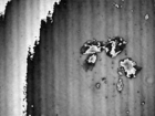
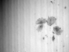
In the Holmos Fourier amplitude view, the first diffraction order is selected as ROI. Then, the captured ("wrapped") phase image is saved on the hard drive. In a separate application, this image is then "unwrapped", e.g. black to white jumps due to the restricted value range of -π to π are removed. | |||
[[File:Holmos emulator.jpg|thumb|363x363px|Fourier amplitude view in the Holmos UI. The blue rectangle is moved to encompass the first diffraction order and surrounding frequences stemming from the interference of the reference beam and light passing the sample.|none]] | |||
=== Results === | |||
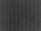
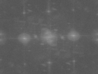
<gallery widths="140" heights="140" perrow="2" caption="Quantitative phase image reconstructed from a cheek cell hologram."> | |||
File:Holmos cheek interference.png|Interference image captured by the camera | |||
File:Holmos cheek fft.png|Fourier amplitude in which the information of interest is encoded in the frequencies around the first diffraction order | |||
File:Holmos cheek wrapped.png|Wrapped phase image reconstructed from the ROI in the Fast Fourier Transform | |||
File:Holmos cheek unwrapped.png|Unwrapped phase image | |||
</gallery> | |||
=== Challenges === | |||
Latest revision as of 16:03, 18 January 2024
| ProjectInfoBox Digital Holographic Microscope | |
|---|---|
| |
| Status: | being built |
| Initiator: | Patrick, Lennart |
Introduction
Holmos
This project is based on project Holmos (https://github.com/holmos-ipm) by Fraunhofer IPM.
Digital Holographic Microscopy
Wikipedia https://en.wikipedia.org/wiki/Digital_holographic_microscopy
This file explains the constraints in optical adjustment https://github.com/holmos-ipm/holmos-hardware/blob/master/instructions/optics_design.md
Assembly
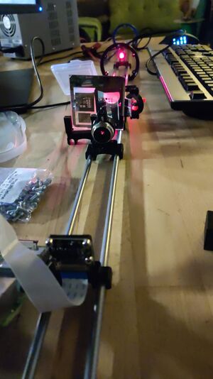
Mounts for the optical components can be printed from files provided in the project repo. These can then be axially moved on metal beams. A Raspberry Pi camera is used for imaging. It is connected to a Raspberry Pi that performs the phase image reconstruction.
Usage
Key steps are
- Position the components according to https://github.com/holmos-ipm/holmos-hardware/blob/master/reference_assembly.py
- Adjust slide holder or objective to get a focused image from the objective beam only
- Direct the reference beam onto the camera sensor
Further practical instructions are given in https://github.com/holmos-ipm/holmos-hardware/blob/master/instructions/adjustment.md
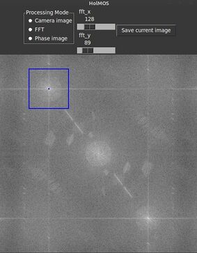
In the Holmos Fourier amplitude view, the first diffraction order is selected as ROI. Then, the captured ("wrapped") phase image is saved on the hard drive. In a separate application, this image is then "unwrapped", e.g. black to white jumps due to the restricted value range of -π to π are removed.
Results
- Quantitative phase image reconstructed from a cheek cell hologram.
-
Interference image captured by the camera
-
Fourier amplitude in which the information of interest is encoded in the frequencies around the first diffraction order
-
Wrapped phase image reconstructed from the ROI in the Fast Fourier Transform
-
Unwrapped phase image
