Project:Digital Holographic Miocroscope: Difference between revisions
Add results gallery |
mNo edit summary |
||
| Line 40: | Line 40: | ||
=== Results === | === Results === | ||
<gallery widths="140" heights="140" perrow=" | <gallery widths="140" heights="140" perrow="2" caption="Quantitative phase image reconstructed from a cheek cell hologram."> | ||
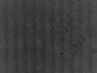
File:Holmos cheek interference.png|Interference image captured by the camera | File:Holmos cheek interference.png|Interference image captured by the camera | ||
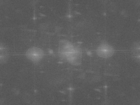
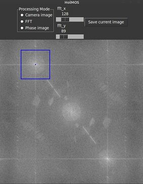
File:Holmos cheek fft.png|Fourier amplitude in which the information of interest is encoded in the frequencies around the first diffraction order | File:Holmos cheek fft.png|Fourier amplitude in which the information of interest is encoded in the frequencies around the first diffraction order | ||
Revision as of 13:39, 18 January 2024
| ProjectInfoBox Digital Holographic Microscope | |
|---|---|
| |
| Status: | being built |
| Initiator: | Patrick, Lennart |
Introduction
Holmos
This project is based on project Holmos (https://github.com/holmos-ipm) by Fraunhofer IPM.
Digital Holographic Microscopy
Wikipedia https://en.wikipedia.org/wiki/Digital_holographic_microscopy
This file explains the constraints in optical adjustment https://github.com/holmos-ipm/holmos-hardware/blob/master/instructions/optics_design.md
Assembly
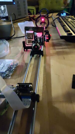
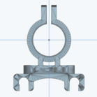
Mounts for the optical components can be printed from files provided in the project repo. These can then be axially moved on metal beams. A Raspberry Pi camera is used for imaging. It is connected to a Raspberry Pi that performs the phase image reconstruction.
Usage
Key steps are
- Position the components according to https://github.com/holmos-ipm/holmos-hardware/blob/master/reference_assembly.py
- Adjust slide holder or objective to get a focused image from the objective beam only
- Direct the reference beam onto the camera sensor
Further practical instructions are given in https://github.com/holmos-ipm/holmos-hardware/blob/master/instructions/adjustment.md
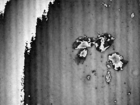
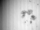
In the Holmos Fourier amplitude view, the first diffraction order is selected as ROI. Then, the captured ("wrapped") phase image is saved on the hard drive. In a separate application, this image is then "unwrapped", e.g. black to white jumps due to the restricted value range of -π to π are removed.
Results
- Quantitative phase image reconstructed from a cheek cell hologram.
-
Interference image captured by the camera
-
Fourier amplitude in which the information of interest is encoded in the frequencies around the first diffraction order
-
Wrapped phase image reconstructed from the ROI in the Fast Fourier Transform
-
Unwrapped phase image
