(4 intermediate revisions by the same user not shown)
Line 26:
Line 26:
You can find the newest version of these required files [https://github.com/comakingspace/WorkBee/tree/master here]. Feel free to submit improvements.
You can find the newest version of these required files [https://github.com/comakingspace/WorkBee/tree/master here]. Feel free to submit improvements.
* At the top of the Fusion 360 Interface, select "Manage > Machine Library".
* at the top of the Fusion 360 Interface, select "Manage > Machine Library".
* Under "My Machines > Local" you can '''''import''''' (NOT CREATE) the machine definition.[[File:Fusion 360 - import machine definition.jpg|alt=Fusion 360 - import machine definition|thumb]]
* under "My Machines > Local" you can '''''import''''' (NOT CREATE) the machine definition. (Filename: WorkBee.mch from the GitHub link above).
* the "Rebuilt WorkBee Comakingspace CNC" will appear, with a red exclamation mark indicating "file not found". This is the '''post processor''', which you will now also need to import:
'''Also separately import the post processor!''' Under the machine entry in your machine library in the "Post:" section, you can click the folder icon to import the latest post processor from the GitHub page.
* click on the folder icon next to "file not found" and the "Post Library" window will open.
* click on the "Import" icon and select the CPS file (Filename: coms-workbee.cps) from the GitHub link above.
* click "select", which brings you mach to the Machine Library import window. There should now be a green tick mark next to "Post: coms-workbee.cps"
<gallery>
<gallery>
File:Fusion360 Machine Library.png|Step 1: Open Machine Library (german Screenshot)
File:Fusion360 Machine Library.png|Step 1: Open Machine Library (german Screenshot)
Line 36:
Line 37:
</gallery>
</gallery>
==== Create your Milling Tool ====
==== Create your Milling Tool inside Fusion's Tool Library ====
At the top of the Fusion 360 Interface, select "Manage > Tool Library" to open the tool library. Navigate to "Local > Library". This is where you'll save all of your endmill data.
At the top of the Fusion 360 Interface, select "Manage > Tool Library" to open the tool library. Navigate to "Local > Library". This is where you'll save all of your endmill data.
* '''Tab 1: General''' Here you can name your endmill. Describe them well, you'll mix them up otherwise. Also enter sourcing information (such as aliexpress links) here, you'll thank yourself later.
* '''Tab 2: Cutter''' Take Measurements of your tool for dimensions using calipers (Messschieber) and populate the values accordingly. Adjust number of flutes and the geometry to match your endmill. I recommend setting "length below holder", "shoulder length" and "flute length" to the same value, that being the length of fully formed cutting flutes of your endmill.
* '''Tab 3: Shaft''' leave as is
* '''Tab 4: Holder''' leave as is
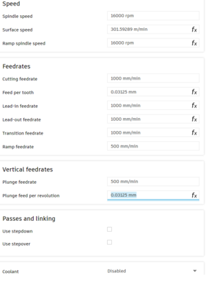
* '''Tab 5: Cutting Data''' The following cutting data is a recommended starting point for a 1/8” (3.175mm) 2-flute flat nose endmill cutting plywood. Many of the values (marked with ''fx'') are calculated automatically and don't need adjusting.[[File:F360-tool-cutting-data.png|thumb]]Tweak these values as you gain experience:
** '''Coolant:''' ''DISABLE'' (To prevent errors, the WorkBee doesn’t have a coolant system)
* '''Tab 6: Post Processor''' leave as is.
Here you can name your endmill. Describe them well, you'll mix them up otherwise. Also enter sourcing information (such as aliexpress links) here, you'll thank yourself later.
Sanity check all data once over and click "accept" to confirm.
'''Tab 2: Cutter'''
Take Measurements of your tool for dimensions using calipers (Messschieber) and populate the values accordingly.
Adjust number of flutes and the geometry to match your endmill. I recommend setting "length below holder", "shoulder length" and "flute length" to the same value, that being the length of fully formed cutting flutes of your endmill.
'''Tab 3: Shaft'''
leave as is
'''Tab 4: Holder'''
leave as is
'''Tab 5: Cutting Data'''
[[File:F360-tool-cutting-data.png|thumb|375x375px|Cutting Data Tab]]
The following cutting data is a recommended starting point for a 1/8” (3.175mm) 2-flute flat nose endmill cutting plywood.
Many of the values (marked with ''fx'') are calculated automatically and don't need adjusting.
This page is a step-by-step walkthrough for setting up a contour milling operation in Autodesk Fusion for the WorkBee CNC specifically, but it should be easy to adapt this to any similar machine.
You will start with a New Fusion 360 Document and end up with a G-Code file ready to upload to the machine.
To get started, you will need to create the 2D geometry you’d like to mill out.
For testing, a simple square with about 50 mm side length is a good starting point.
Extrude it by the material thickness you plan to machine.
example test part
In the top left corner of Fusion 360, switch from the “Design” workspace to the “Manufacture” workspace. This is where you’ll define your toolpaths and machine settings.
Import Workbee CNC machine definition
Before you get started, make sure you have properly imported the latest version of the machine definition and post-processor into Fusion 360.
You can find the newest version of these required files here. Feel free to submit improvements.
at the top of the Fusion 360 Interface, select "Manage > Machine Library".
under "My Machines > Local" you can import (NOT CREATE) the machine definition. (Filename: WorkBee.mch from the GitHub link above).
the "Rebuilt WorkBee Comakingspace CNC" will appear, with a red exclamation mark indicating "file not found". This is the post processor, which you will now also need to import:
click on the folder icon next to "file not found" and the "Post Library" window will open.
click on the "Import" icon and select the CPS file (Filename: coms-workbee.cps) from the GitHub link above.
click "select", which brings you mach to the Machine Library import window. There should now be a green tick mark next to "Post: coms-workbee.cps"
Step 1: Open Machine Library (german Screenshot)
Step 2: Import machine to local machines
Create your Milling Tool inside Fusion's Tool Library
At the top of the Fusion 360 Interface, select "Manage > Tool Library" to open the tool library. Navigate to "Local > Library". This is where you'll save all of your endmill data.
Click on "[+]" to add a new tool. Select the appropriate geometry, most likely "Flat End Mill".
The tool creation menu
Tab 1: General Here you can name your endmill. Describe them well, you'll mix them up otherwise. Also enter sourcing information (such as aliexpress links) here, you'll thank yourself later.
Tab 2: Cutter Take Measurements of your tool for dimensions using calipers (Messschieber) and populate the values accordingly. Adjust number of flutes and the geometry to match your endmill. I recommend setting "length below holder", "shoulder length" and "flute length" to the same value, that being the length of fully formed cutting flutes of your endmill.
Tab 3: Shaft leave as is
Tab 4: Holder leave as is
Tab 5: Cutting Data The following cutting data is a recommended starting point for a 1/8” (3.175mm) 2-flute flat nose endmill cutting plywood. Many of the values (marked with fx) are calculated automatically and don't need adjusting.Tweak these values as you gain experience:
Spindle Speed (Drehzahl): 16,000 RPM
Cutting Feedrate (Schnittvorschub): 1000 mm/min
Ramp Feedrate (Helixvorschub): 500 mm/min
Plunge Feedrate (Eintauchvorschub): 500 mm/min
Coolant:DISABLE (To prevent errors, the WorkBee doesn’t have a coolant system)
Tab 6: Post Processor leave as is.
Sanity check all data once over and click "accept" to confirm.
Configure Setup
Back in the Manufacture workspace window, go to "Setup > New Setup"

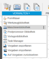 Step 1: Open Machine Library (german Screenshot)
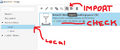 Step 2: Import machine to local machines