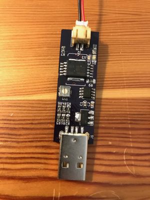
Project:QC3 LED driver
| ProjectInfoBox Quick Charge 3 LED driver | |
|---|---|

| |
| Status: | Done |
| Release Date: | 01.01.1970 |
| Initiator: | Patrick |
| Materials Used: | OSH Park PCBs, electronics from Arrow.com, |
| Tools Used: | Soldering Iron, Hot Air Soldering Station |
| Software Used: | KiCAD |
| Approx. Cost: | ~30€ w/o LEDs & powerbank |
As part of another project to remake the backpack from the Netflix series ‘Altered Carbon‘ (Yes, that one with a unicorn), I needed to design a battery powered LED driver. The LED strip to be powered is the same as used in the movie prop and is running on a 12V supply voltage. A battery with that voltage can either be bought off-the-shelf or or build (e.g. with 3 LiIon batteries in series). However both of these options need quite a bit of safety circuitry and/or come with a special charger making them relatively bulky.
Standard USB power banks are readily available and can be charged via most phone chargers. Their supply voltage however is only 5V which would require a step up module to get to the 12V LED voltage. Some power banks support special charging modes like Quick Charge by Qualcomm or USB power delivery. These allow for for higher voltages (e. g. 12V for QC2/3) on the USB power line, but need a handshake between the supply and the device.
Goal of this project was to make a (small) dongle that requests 12V from a QC3 powerbank and drives the LED strip while allowing dimming and automatic turn on once the backpack has been opened.
Quick Charge handshake
The QC protocol is a proprietary technology by Qualcomm, which is usually implemented in their chipsets. Therefore it is difficult to find a proper documentation on how the protocol works. Luckily there are nice people who reverse-engineered it already and put an Arduino library on GitHub. An in-depth explanation can be found on the blog of the library's author, but the basic are the following:
- After the initial connection the charger shorts D+ & D- data lines
- the device sets 0.6V on D+ for at least 1.25s
- charger removes the short and pulls D- to GND with a 20k resistor
- now different supply voltages can be requested by the device by applying different analog voltages on D- & D+ (5V, 9V, 12V)
- With QC3 these can also be changed in 200mV increments
The analog voltages on the data lines are created with a voltage divider between 5V and GND (10k Ohm, 1.5k Ohm) to which a data line and a microcontroller IO (via 470 Ohm) are attached. Depending on the state of the IO (LOW, HIGH, high impedance) different voltages can be generated on the data line.
- HIGH -> 3.85V
- LOW -> 0.17V
- high impedance -> 0.65V
Circuit
The circuit is made of the following components:
- Voltage divider
- microcontroller (Attiny25)
- LED driver IC (STCS2A)
- Hall effect sensor (DRV5033AJQLPG)
As mentioned before, the voltage divider allows for applying different voltages to the D+ & D- line (mainly 0.6V and 3.6V). The whole system is then controlled by an Attiny25 (Yes, I cheaped out on the flash). The Attiny modulates the LED driver via PWM depending on the value set by a trimmer potentiometer. That way the brightness of the LED strip can be adjusted afterwards. If the Hall effect sensor is close to a strong magnetic field (backpack is closed) it will pull the ENABLE pin of the LED driver low causing it to turn off.
PCB
The PCB layout was kept small and in a form-factor of an USB drive. LEDs and Hall effect sensor need to be routed via cables later on therefore I made them attach via some JST PH2 sockets.
Issues
ISP programming
Even-through the ISP pins were routed to pads the programming of the Attiny didn't work when the PCB was fully populated. My guess is the voltage divider pulls the MISO & MOSI pins to GND with a too low impedance.
Soldermask pullpack
I had accidentally set the solder mask pullback in KiCAD to 0.2mm instead of 0, which caused some trouble as due to pins shorting to GND.