Project:Flip Dot Display: Difference between revisions
(Created page with "An impulse acquisition we made at the Makerfaire Hannover – three 16x24 flip dot displays. The project will be to get them up and running for displaying stuff in and around...") |
(added website to generate hex code) |
||
| Line 13: | Line 13: | ||
* a 500-600 microsecond pulse is sufficient to switch a pixel | * a 500-600 microsecond pulse is sufficient to switch a pixel | ||
* the row and column selection will be done via a couple of shift registers ([http://www.ti.com/lit/ds/symlink/sn74hc595.pdf 74HC595]) | * the row and column selection will be done via a couple of shift registers ([http://www.ti.com/lit/ds/symlink/sn74hc595.pdf 74HC595]) | ||
<gallery> | <gallery> | ||
File:FFD_flip.gif|flipping dot (click to see) | File:FFD_flip.gif|flipping dot (click to see) | ||
| Line 28: | Line 27: | ||
== Stage 0.4 – Alternate Design == | == Stage 0.4 – Alternate Design == | ||
The triac circuit worked with some triacs (Z013MA) however it proved to be rather difficult to implement with higher current triacs (probably due to higher latch current). Therefore I started with a common H-bridge design (L293D). Also I found a cheaper source for them on eBay (~50 cent/piece). | The triac circuit worked with some triacs (Z013MA) however it proved to be rather difficult to implement with higher current triacs (probably due to higher latch current). Therefore I started with a common H-bridge design (L293D). Also I found a cheaper source for them on eBay (~50 cent/piece). | ||
== Generating display code == | |||
The display runs on a simple byte array (1 = yellow). To "draw" an image there are websites like [http://dot2pic.com/ dot2pic]. Select Monochromatic, 8 pixels per byte (horizontal) 24x16 draw. | |||
[[Category:Electronics]] | [[Category:Electronics]] | ||
[[Category:Arduino]] | [[Category:Arduino]] | ||
[[Category:Programming]] | [[Category:Programming]] | ||
Revision as of 18:45, 30 April 2018
An impulse acquisition we made at the Makerfaire Hannover – three 16x24 flip dot displays. The project will be to get them up and running for displaying stuff in and around the CoMakingSpace (hey!). Any aid (e.g. donations for parts) are very welcome! Talk to Patrick for the most recent status of the project or have a glance in the GitHub repository.
Stage 0.1 – The Purchase

Stage 0.2 – Basics and Proof of Concept
The first steps were to run just a few pixels manually and then via a microcontroller. With 12V voltage pulse over a column and a row you can make a pixel switch – pretty much like playing battleships. Depending the direction of the current the pixel either switches to yellow or black.
Things learned from testing:
- the display is usually powered by a dual power supply (e.g. +12V/-12V)
- this can be mediated by switching the voltage with an H-bridge
- H-bridges are a pain in the a** to wire on a breadboard
- a 500-600 microsecond pulse is sufficient to switch a pixel
- the row and column selection will be done via a couple of shift registers (74HC595)
flipping dot (click to see)
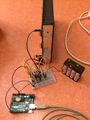
test of the H-bridge


Stage 0.3 – First Circuit Design
Usually FDDs are controlled via a half-H-bridge for each row/column, which then get powered once a dot has to be flipped. However this method is rather expensive in terms of parts needed to run a larger display. You could build a half-H-bridge for every line by yourself, but this would be insanely time consuming and hard to debug, or you could use a quad-motor-driver-chip, which costs 2 to 3 €. This is still not cheap but a reasonable option for a controller board.
Nevertheless I wanted to go for an even cheaper method of controlling the FDD with just a single H-bridge for current flow and a triac for each row/column. A triac works roughly like a transistor for alternating currents (AC). If you apply a current trough the gate of the triac, the impedance between the two anodes decreases drastically and allows flow of current through the triac. This is pretty much exactly what is needed to select a column and a row to flip a dot on the display.
To reduce the need of I/O ports of a microcontroller, a couple of shift registers (74HC595) will serve as a digital I/O extender. This way only 3 pins are needed to control a (nearly) arbitrarily large flip dot display.
Stage 0.4 – Alternate Design
The triac circuit worked with some triacs (Z013MA) however it proved to be rather difficult to implement with higher current triacs (probably due to higher latch current). Therefore I started with a common H-bridge design (L293D). Also I found a cheaper source for them on eBay (~50 cent/piece).
Generating display code
The display runs on a simple byte array (1 = yellow). To "draw" an image there are websites like dot2pic. Select Monochromatic, 8 pixels per byte (horizontal) 24x16 draw.