Project:Counter Board: Difference between revisions
m (some links & categories) |
(links) |
||
| Line 12: | Line 12: | ||
# 1x PCB | # 1x PCB | ||
# 4x 7-segment display | # 4x 7-segment display (common cathode) | ||
# 4x CD4026BE decade counter | # 4x [http://www.ti.com/lit/ds/symlink/cd4026b.pdf CD4026BE] decade counter | ||
# 32x 1k Ohm [ | # 32x 1k Ohm [https://en.wikipedia.org/wiki/Resistor resistor] | ||
# 1x 10k Ohm resistor | # 1x 10k Ohm [https://en.wikipedia.org/wiki/Resistor resistor] | ||
# 2x 100k Ohm resistor | # 2x 100k Ohm [https://en.wikipedia.org/wiki/Resistor resistor] | ||
# 2x 6mm push button | # 2x 6mm push button | ||
# 2x 100nF [ | # 2x 100nF [https://en.wikipedia.org/wiki/Capacitor capacitor] | ||
# 1x [ | # 1x 1N4004 [https://en.wikipedia.org/wiki/Diode diode] | ||
# 1x [[switch]] | # 1x [[switch]] | ||
# 1x 9V battery clip | # 1x 9V battery clip | ||
Latest revision as of 13:33, 16 November 2018
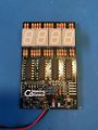
The counter board is a little electronics and soldering kit, which is designed for people interested in learning a bit about electronics and soldering. It is essentially a digital version of those mechanical tally counters.
If you are interested in building one for yourself you can ask one of the managers. Please keep in mind the kit costs around 6€ in material (PCB & components), a small donation would be awesome!
Assembly
Components
These are the components that are needed to assemble the board. Check that nothing is missing from your kit before you get started!

- 1x PCB
- 4x 7-segment display (common cathode)
- 4x CD4026BE decade counter
- 32x 1k Ohm resistor
- 1x 10k Ohm resistor
- 2x 100k Ohm resistor
- 2x 6mm push button
- 2x 100nF capacitor
- 1x 1N4004 diode
- 1x switch
- 1x 9V battery clip
Soldering
All the components on the board are through-hole technology (THT) components and are therefore soldered in a similar way. Bend the leads of the component so it can fit through the correct footprint on the board. For the resistors it help to bend them back a little afterwards so they won't fall out again. To solder the leads to the board, try to heat the pad on the board with the soldering iron and apply solder to it. It should form a solder joint around the lead. Afterwards the leads can be trimmed with a side cutter.
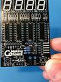
Step 1 - 10k & 100k resistors
The two 100k resistors go on R1 and R3 (the two on the top) and the 10k Ohm resistor goes on R2.
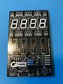
Step 2 - Diode
The diode goes on the bottom of the board (D5). Make sure the orientation is as indicated on the board with the white ring on the left side.
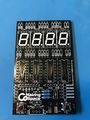
Step 3 - Buttons
Place the buttons on their locations in the bottom corners.
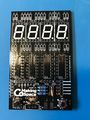
Step 4 - Capacitors
The two 100nF capacitors go on C1 and C2. They are used to avoid multiple counts due to bouncing of the "+1" button.
Step 5 - Switch
The switch goes on the bottom in the small rectangle.
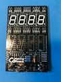
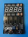
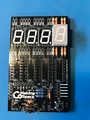
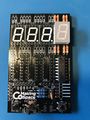
Step 6 - Resistors and 7-segment displays
The 1k resistors and 7 segment displays go on the remaining indicated locations on the top of the board. Be aware of the orientation of the displays. The decimal point should be on the bottom, otherwise the display won't work! If you chose not to solder all the 7-segments, start from the right side of the board (as seen in the images).
Step 7 - ICs
The next step is to solder the CD4026 to its location. Also with this component make sure it is oriented correctly with the notch on the top.
Repeat the last two steps until the board is fully populated.
Step 8 - Battery connector
The circuit was designed to run off a 9V battery, therefore the last step is to solder the battery connector to the + & - terminals on the bottom. Feed the cables through the two holes to serve as a strain relieve. Red goes to + and black to -.
Step 9 - Test it!
Attach a 9V battery and see if everything works as intended. If not, check your solder joints and the orientation of the components.
Step 1
Step 2
Step 3
Step 4
Step 5
Step 6a
Step 6b
Step 7
Step 8


Circuit
- will be soon on a GitHub near you*